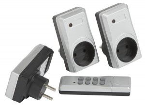
So I have one of these cheap remote controlled outlets, and I just finished my IR remote control project with the Raspberry Pi, so why not try to control these with the Raspberry Pi also?

How does it work?
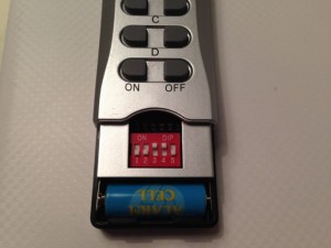
The way these outlets work, is you set some dip-switches on the remote, and on the outlets so they match.
Creating RF transmitter / receiver
Source: http://shop.ninjablocks.com/blogs/how-to/7506204-adding-433-to-your-raspberry-pi
I bought my RF transmitter and receiver from eBay a about 1$.
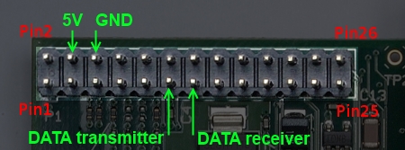
Connecting RF transmitter and receiver to the Raspberry Pi is pretty simple.
Both the reciver and transmitter has a VCC, GND and DATA pins.
And all you do is connect it to the Raspberry Pi GPIO pins.

Install RPi_utils
Source: https://github.com/ninjablocks/433Utils/tree/master/RPi_utils
Start by installing RPI_utils
sudo apt-get update

#Installs GIT
sudo apt-get install git
sudo apt-get install git-core

#Installs 433util
git clone git://github.com/ninjablocks/433Utils.git
cd 433Utils/RPi_utils/

#Installs wiringPI
git clone git://git.drogon.net/wiringPi
cd wiringPi
git pull origin
./build

#Builds RPI_util
cd ..
make all
Testing and decoding RF signal
To capture and decode the RF signal from the remote, I ran the program RFSniffer.
sudo ./RFSniffer
When I push the A (on) button on the remote, I get the following code on the screen.
Received 5260625
Received 5260625
Received 5260625
Received 5260625
Received 5260625
To test if the transmitter works you can send the received value with this command.
sudo ./codesend 5260625
If you convert 5260625 to binary, you get 10100000100010101010001.
And looking at the binary value of all the buttons, you start to see a pattern.
| Button | Decimal value | Binary value |
| A (On) | 5260625 | 10100000100010101010001 |
| A (Off) | 5260628 | 10100000100010101010100 |
| B (On) | 5263697 | 10100000101000101010001 |
| B (Off) | 5263700 | 10100000101000101010100 |
| C (On) | 5264465 | 10100000101010001010001 |
| C (Off) | 5264468 | 10100000101010001010100 |
| D (On) | 5264657 | 10100000101010100010001 |
| D (Off) | 5264660 | 10100000101010100010100 |
They all starts with 1010000010, and all the ON buttons ends with 0001 and all the OFF buttons ends with 0100.
The 1010000010 matches with the dip-switches; 10 = down and 01 = up.
The middle part, is a value that identifies A,B,C and D.
You can see the pattern here:
| Dip switch | Button Id | On / Off | ||||
| A | = | 10 10 00 00 10 | + | 00 10 10 10 1 | + | 0001 / 0100 |
| B | = | 10 10 00 00 10 | + | 10 00 10 10 1 | + | 0001 / 0100 |
| C | = | 10 10 00 00 10 | + | 10 10 00 10 1 | + | 0001 / 0100 |
| D | = | 10 10 00 00 10 | + | 10 10 10 00 1 | + | 0001 / 0100 |
Script
I then created the following bash script.
#!/bin/bash
BTN=$1
STATUS=$2

BTN=$(echo $BTN | tr '[:lower:]' '[:upper:]')
STATUS=$(echo $STATUS | tr '[:lower:]' '[:upper:]')

DIP_SWITCH="DDUUD"  #Change dip switches to match the remote

#hardcoded values
BTN_A="001010101"
BTN_B="100010101"
BTN_C="101000101"
BTN_D="101010001"

DIP_SWITCH=$(echo $DIP_SWITCH | sed 's/D/10/g' | sed 's/U/00/g')

case $BTN in
    A )
        BTN=$BTN_A ;;
    B )
        BTN=$BTN_B ;;
    C )
        BTN=$BTN_C ;;
    D )
        BTN=$BTN_D ;;
    * )
        echo "Please define the button [A-D]";exit;
esac
case $STATUS in
    ON )
        STATUS="0001" ;;
    OFF )
        STATUS="0100" ;;
    * )
        echo "Please define the button state [ON/OFF]";exit;
esac

BIN=$(echo $DIP_SWITCH$BTN$STATUS)
DEC=$((2#$BIN))

#echo $DEC
sudo /home/pi/codesend $DEC
And to emulate a click, I just call
./RFISend.sh A ON
Control via web
Because the codesend uses wiringpi, it is required to call with sudo.
But if you need to call it from a webserver, it creates some problem, because sudo requires a password.
So we need to edit visudo, so it doesn’t require a password.
(it may not be a secure thing to do, but in my case the webserver is not exposed to the internet, and is only for “at home” use)
sudo visudo
Add the following line to the file.
#NOTE: use TAB and not space, except for the last one – after NOPASSWD:
www-data ALL=(root) NOPASSWD: /home/pi/433Utils/RPi_utils/codesend
Save the file and reboot the Raspberry Pi, and you’re good to go.
Now the local PHP webserver can call the script with:
<?php
  shell_exec("/home/pi/433Utils/RPi_utils/RFISend.sh A ON");
?>


Hello,
Tried sudo ./RFSniffer but no code are showed eventhough my test led is blinking when i push the A button of my remote controller.
Any clue ?
Be sure that your RF receiver frequency matches your remote.
I’m not sure how you have attached the RF receiver.. but I was able to read the signal, by attaching the receiver directly to the GPIO. With no extra components.
So try to connect only the RF receiver as described. (5+, Gnd, DATA receveiver pin)
Hi,
I think there is a mistake, the 5V is at the first left not second.
But good tutorial, thanks. 🙂
thanks, 5 V is both the first and second 🙂
pin 2 and 4
http://elinux.org/RPi_Low-level_peripherals#General_Purpose_Input.2FOutput_.28GPIO.29
Thanks,
work fine
Hi,
Great tutorial, I have a problem though where the sniffer gets the code fine; when I send out the code from the program it has no action. I tested it with another remote and that one works fine. Any ideas why this might be?
not really sure, but did you get a consistance value from the sniffer?
What I mean is if you press the button multiple times with the sniffer, do you get the same value every time?
I’m thinking maybe there some noise, that the sniffer picks up.
Or maybe your RF-sender doesn’t match your remote.
I had one of the buttons that didn’t give the same result with the sniffer. That’s why I did the analysis with the binary values, to figure out what value to use.
Same code receives every time, when the code is sent from the Pi; it doesn’t do anything.
Could it be the pulse length? Is there a way to determine the length from the code/receiver?
I don’t know.
I’ve only tried it with one remote. And with that, all buttons worked.
I haven’t got into the RFSniffer code, so I don’t really know what it does.
Could you post the values for on/off for all the buttons?
The 433Utils has some issues in that it assumes that there is a consistent time block with multiples. Have a look at my blog https://danicymru.wordpress.com/2016/12/15/433mhz-rf-nexa-sockets-and-the-blyss-wireless-doorbell/ which may help you with your issues.
Hi, how to get the value in RFSniffer, to process the RF data? because i can see in the console the value that recive, but i cant put for example
if “RF data” = 123456
turn on the light
The RFSniffer can only capture the RF signal.
If RFsniffer returns 1234656, then to use it you run:
sudo ./codesend 123456Hi would the wiring schematics work with Raspberry Pi2 as well?
I have not tried it. But I believe the use the same pins.
This is sort of a rookie question but what’s the “tightest” way to connect those RF Transmitter and Receiver boards you pointed to to a RaspberryPI? I’m trying to make about 30 of these and I’d love to be able to connect the tiny boards to the GPIO pins by just pressing them on
Not sure what you mean. You’ll need a connector and some wires. It should be relative small.
Great work! I just wanted to point somethings out about your signaling section. The remotes are using a PT2262 encoder compatible fixed codeword. It uses a two pulse tribit waveform with a total length of 12; 5 address bits, 5 ID data bits, and 2 function bits (plus 1 sync bit which is not representable). This binary conversion of 00 is tribit 0, 11 is tribit 1, and 01 is tribit F (float). Thus each “bit” are represented in pairs (12 tribits x 2 = 24 digits). Your binary representation 10100000100010101010001 is only partially correct; it’s only 23 digits (your converter dropped the first 0), and 10 cannot be represented in this particular waveform. In practice it will work because 433utils will take the decimal value and output the corrected binary representation. The first 5 sets of the codeword are the address / channel, because (cheap) dip switches cannot represent tribit, they can only be represented by 2 of the 3 possibilities (your remote manufacturer went with 00 and 01, but different combinations of tribits can be used depending on the manufacture). The next 5 tribits are ID, all bits here have to be tribit F (01) except for one tribit 0 (00), this will give you a total of 5 IDs A through E. Your table is thrown off by just one digit. You are correct that the last two tribits are the latch / interlocking functions, tribits 0F for on and F0 for off (again I’ve seen some manufacturers flip these). In reality none of this really matters with newer “learning” remotes or 2262 knockoffs, they pretty much accept anything.
I can’t seem to “make all”. Any ideas?
pi@raspberrypi:~/433Utils/RPi_utils $ make all
make: *** No rule to make target ‘../rc-switch/RCSwitch.o’, needed by ‘send’. S
Not sure. I’m not familiar with that error. Sorry
If anyone else sees this error, its because the rc-switch folder is actually empty. There is an issue with the current git repository that pulls a completely empty directory.You need to go into the directory on git and grab the url from there to pull it direct
git://github.com/sui77/rc-switch.git
After this place the folder in the proper location and you should be able to make just fine.
Hello, I think that it is very nice. Could we make our own code like that?
Thank you! But I’m not sure what you mean?
Thank you for tutorial . Keep support for this website .