BTHome Electricity Meter for Home Assistent

I wanted to track my electric usage in real-time, and I’ve already have Home Assistant as my main smart home management system, so I wanted to make use of the Energy tracking feature that it provides.

Because my meter is located outside our house, I had to find a solution that runs on batteries.

I was looking into the Frient electricity meter, but couldn’t find any available anywhere. So I searched and found this DIY smart meter https://www.espruino.com/Smart+Meter

And to prolong the battery-life, I’m using 2 x D batteries instead of the small CR2032 battery.

UPDATE: After a couple of month using this. It became very unstable. It keept loosing connection to Home Assistant.
I ended up buying the Frient Electricity Meter Interface 2 – and this has been working perfectly.

What you need

  • Puck.js
  • LDR sensor (GL5537)
  • 2 x 15mm ring magnets
  • D battery holder
  • 2 x D batteries
  • wire / 3d-printer
  • optional: jst connector for the wire

3D printed casing

I started with 3d printing the casing for the LDR sensor and the Puck.JS
STL: https://www.printables.com/model/376244-puckjs-case-for-electricity-monitoring

I divided it in 3 part, for easier print.
– Casing for the LDR sensor and Puck.JS
– Magnet holder
– Meter alignment-piece, to block out any outside ligth when attached to the meter

Assembly

I started with removing the battery clip and the button from the Puck, for it to be more low-profile

– Put doublesided tape on one of the magnets, and attach it on the meters led.
– Solder the LDR and battery-connecter / wires together.
– Assemble the 3 3d printed pieces by glueing them together.

I added a red cap, so that the Puck’s led could shine throgh.
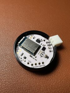
Coding

Get the code for the puck from github: https://github.com/aegjoyce/bthome-electricity-meter

You need to adjust the imp variable to match your meters. It should be printed on your meter. Something like: 1000 imp/kWh

If your Home assistant is setup correctly, it will find the device automatically.
Uptime robot-robot

So.. 3 years with no posts .. wow..

aaaanyway…

My better half works with web sites and hosting. They rely on the service of UptimeRobot to notify them if any of their sites is down.

I though it would be fun, to create something physical, that could maybe blink or something.

Introducing.. The UptimeTimeRobot-robotstill working on the name 😉

When the “robot” is connected to wifi, it will just sit there and blink every once in a while.

But whenever a server is down, we get this.

At the top, there’s a button to pause the alert until next cycle, where it calls the uptime robot api.

Click: Pause the alert until next cycle.
5 sec. press: Reset wifi settings.
10 sec. press: Checks for new firmware OTA

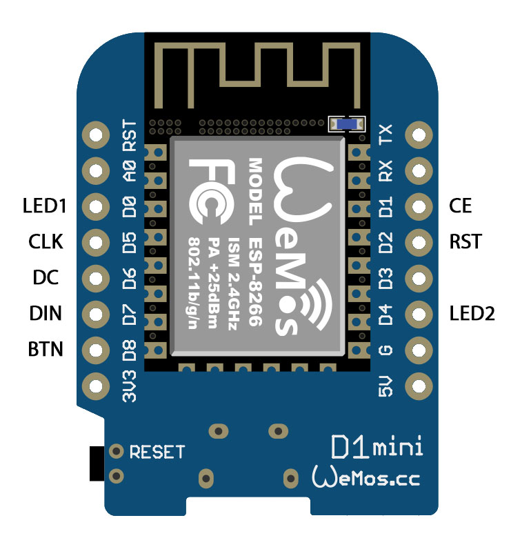
The body is 3d printed, and the interior is
– 1 x 5110 lcd display
– 1 x wemos d1
– 1 x push button
– 2 x leds (red and blue)

And here’s how it’s wired together:

Source code can be found here: https://github.com/kim82/esp8266UptimeRobot

Homebridge with Sonoff

Sonoff

I bought two of those cheap wifi remote controlled switches called Sonoff.
These switches allow you to turn them on and off with an app on your phone.
https://www.itead.cc/sonoff-wifi-wireless-switch.html

Inside these switches are a ESP8266 , which means that we can flash the chip with our own custom firmware.
And with the help of a Raspberry pi we can enable homekit.

Firstly I reflashed the sonoff with my custom firmware, using the Arduino IDE. (Google how to flash ESP8266)
(This disables the use of the official sonoff app)

https://github.com/kim82/sonoff

Remember to change the hostname, if you have multiple sonoff.

#define HOSTNAME        "sonoff_00"

Raspberry Pi – Homebridge

Download and install Raspbian on the Raspberry Pi.
https://www.raspberrypi.org/downloads/raspbian/

When this is done we can install Homebridge, which is the service that sits between your apple devices and the sonoff switch.

The full install guide can be found here:
https://github.com/nfarina/homebridge/wiki/Running-HomeBridge-on-a-Raspberry-Pi

TLDR; (Raspberry Pi 3)

sudo apt-get update
sudo apt-get upgrade
sudo apt-get install git make
sudo apt-get install g++
#install node
curl -sL https://deb.nodesource.com/setup_8.x | sudo -E bash -
sudo apt-get install -y nodejs
#install Avahi and other dependencies
sudo apt-get install libavahi-compat-libdnssd-dev

Script2

Next we need to install Script2, which is a homebridge plugin that allows you to run bash-scripts though the homebridge

npm install -g homebridge-script2

Start at bootup

Lastly we need to start Homebridge whenever the Raspberry pi boots up.
And the following method was found here:
https://gist.github.com/johannrichard/0ad0de1feb6adb9eb61a/

We need to create the following two files.

/etc/default/homebridge

# Defaults / Configuration options for homebridge
# The following settings tells homebridge where to find the config.json file and where to persist the data (i.e. pairing and others)
HOMEBRIDGE_OPTS=-U /var/lib/homebridge

/etc/systemd/system/homebridge.service

[Unit]
Description=Node.js HomeKit Server 
After=syslog.target network-online.target

[Service]
Type=simple
User=homebridge

#could be /usr/local/bin/homebridge - check where the homebridge folder exists
EnvironmentFile=/etc/default/homebridge 

ExecStart=/usr/bin/homebridge $HOMEBRIDGE_OPTS
Restart=on-failure
RestartSec=10
KillMode=process

[Install]
WantedBy=multi-user.target

And to enable the newly created service. (first time only)

sudo systemctl daemon-reload
sudo systemctl enable homebridge
sudo systemctl start homebridge

We also need to create a new user and the folder for the config.json file

#create a new user
sudo useradd -M --system homebridge

#creates a new folder
sudo mkdir /var/lib/homebridge

#changes the owner of the folder to new homebridge-user
sudo chown homebridge:homebridge /var/lib/homebridge

Configuration

To configure the script2, we need to create a config.json file in the /var/lib/homebridge folder.

Mine looks like this:

{
    "bridge": {
        "name": "Sonoff",
        "username": "AA:BB:CC:DD:EE:FF", (THIS NEEDS TO BE CHANGED)
        "port": 40500,
        "pin": "XXX-XX-XXX" (THIS NEEDS TO BE CHANGED - WITH NUMBERS)
    },

    "description": "Sonoff Homebridge",

    "accessories": [
                    {
                    "accessory": "Script2",
                    "name": "Bedroom lamp",
                    "on": "curl http://sonoff_00.local/on",
                    "off": "curl http://sonoff_00.local/off",
                    "state": "curl --max-time 1 http://sonoff_00.local",
                    "fileState": "",
                    "on_value": "on"
                    },
                    {
                    "accessory": "Script2",
                    "name": "Living room lamp",
                    "on": "curl http://sonoff_01.local/on",
                    "off": "curl http://sonoff_01.local/off",
                    "state": "curl --max-time 1 http://sonoff_01.local",
                    "fileState": "",
                    "on_value": "on"
                    }
                   ],

    "platforms": []
}

Restart the homebridge service

sudo systemctl restart homebridge

Now you should be able to add the sonoff homebridge to your Home-app on the iphone/ipad, and control the switches.

GIF frame – IOS app

My first idea was to add a ESP8266 to the GIF frame, so that I could control it remotely. But I haven’t had much success when tinkering the it. I can not get it to run a webserver without it freezing up.

But I had a Bluetooth Low Energy (BLE) laying around – Yes, I have a lot a stuff laying around 🙂
I had bought it a while ago, but didn’t really got into code in Cocoa Touch for iOS- also I didn’t want to pay 100$ for the developer subscription – which was needed for you to get the app on the iPhone.

But with the latest release of xcode, you can install your own apps on your iPhone without the subscription! So everything kinda came together for this project 🙂

The BLE device communicates with a serial port, and can talk directly to the Arduino.
I just need some small adjustments to the menu code – adding software serial. (and I included a power on/off option, while I was at it)

Download: GIF frame

And here it is:

GIF frame – software

The software for the animated gif frame, consist of 3 parts.

  1. code for the Arduino, that reads the sd-card and displays it on the ledstrips (main board)
  2. code for the Arduino, that runs the LCD menu (menu)
  3. code on the PC, which converts a GIF into a text file, with the color codes of the GIF.

Arduino sketch

The two Arduinos communicates via the serial ports.
At startup the main board, request the menu for the current settings. (it does this by sending a request_signal)

Serial.write(REQUEST_DATA);       // request for new data    - value is 155

The menu, then sends the settings in the following format

Serial.write(START_SIGNAL);       // 111
Serial.write(loadNext ? 1 : 0);   // next                    - values 0 or 1
Serial.write(menu.mode);          // mode (single/slideshow) - values 0 or 1
Serial.write(menu.repeat);        // slideshow duration      - values 1 to 50
Serial.write(menu.speed);         // speed                   - values 10 to 100
Serial.write(menu.brightness);    // brightness              - values 10 to 60
Serial.write(END_SIGNAL);         // 222

Whenever a change in the menu happens, it will also send this byte array to the main board.
The menu also,saves the changes to EPROM, so that the settings can be restored when power off and on.

Download the sketch + xcode here: GIF frame

PC software

On the PC side, I used this Processing sketch, but I think i really is just Java. Kinda like Arduino sketch is C/C++.
https://github.com/MeULEDs/MeU_Square_GIF_Converter_Teensy

I modified the original code, so I only outputs the color codes, and not the Arduino sketch code.
Here is my version: GIF_Converter.pde